


 61 / 84

54
7.4
7.4
7.4
6.3
6.3
6.3
21.5
21.5
21.5
7.9
7.9
7.9
8.0
8.0
8.0
10.0
10.0
14.0
2.7
3.3
4.5
1.7
2.3
3.4
L
F
D
d
W1
W
E
Plate Shape Pre-insulation Terminal
Item No .
Dimension
(mm)
Color
W L
F1
D d
Wire Range
2
mm (
AWG
)
W1
F
E
Thickness
Of Material
(mm)
PBDD 1.25-250
0.40
0.5-1.5
(22-16)
PBDD 2-250
0.40
PBDD 5.5-250
0.40
1.5-2.5
(16-14)
4-6
(12-10)
FDD 1.25-110(8)
FDD 1.25-187(8)
FDD 1.25-250
0.8
×
2.8
0.8
×
4.75
0.8
×
6.35
0.30
0.35
0.40
3.8
5.6
7.4
19.0
19.0
21.0
6.4
6.5
7.9
Item No .
Dimension
(mm)
Color
Wire Range
2
mm (
AWG
)
NEMA
Tab
Thickness
Of Material
(mm)
d
B L F H D
10.0 3.8 1.7
Female Pre-insulation Splice
FDD 2-110(8)
FDD 2-187(8)
FDD 2-250
0.8
×
2.8
0.8
×
4.75
0.8
×
6.35
0.30
0.35
0.40
3.8
5.6
7.4
19.0
19.0
21.0
6.4
6.5
7.9
10.0 4.3 2.3
FDD 5.5-250
0.8
×
6.35
12.5 5.7 3.4
0.40 7.4 25.0 7.9
0.5-1.5
(22-16)
1.5-2.5
(16-14)
4-6
(12-10)
B
H
L
dØ
DØ
F
Item No .
Dimension
(mm)
Color
Wire Range
2
mm (
AWG
)
NEMA
Tab
Thickness
Of Material
(mm)
d
B L H D
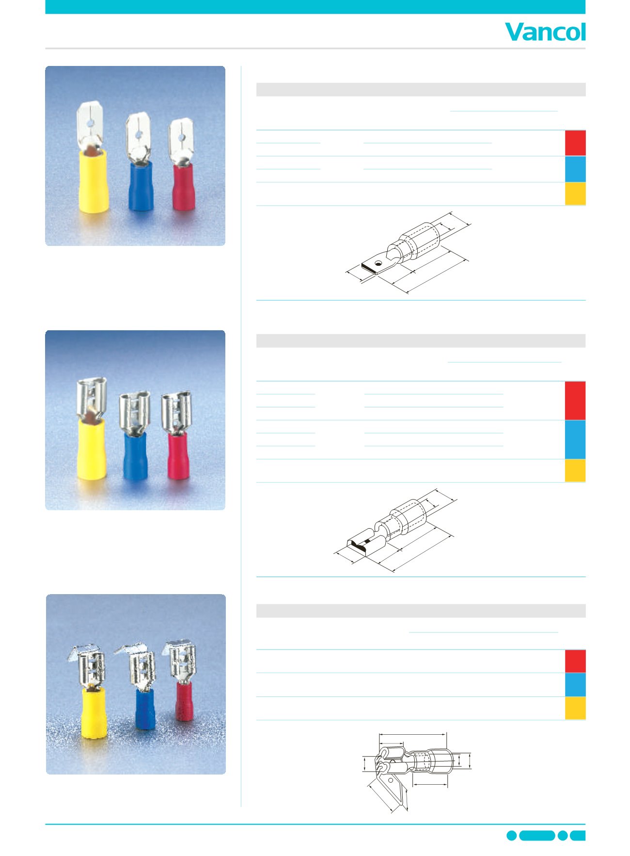
Male Pre-insulation Splice
MDD 1.25-187(8)
MDD 1.25-250
0.8
×
4.75
0.8
×
6.35
0.40
0.40
4.75
6.35
18.5
21.0
10.0 3.8 1.7
MDD 2-187(8)
MDD 2-250
0.8
×
4.75
0.8
×
6.35
0.40
0.40
4.75
6.35
18.5
21.0
10.0 4.3 2.3
MDD 5.5-250
0.8
×
6.35
12.5 5.7 3.4
0.40 6.35 25.0
0.5-1.5
(22-16)
1.5-2.5
(16-14)
4-6
(12-10)
B
H
L
dØ
DØ
F